Industrial Thermocouple Failure Analysis & Sensor Diagnostics
Thermocouples are widely throughout industry to make process temperature measurements. These measurements control any number of different process variables: temperature, flow rate of fluids, heater input power, pressure, etc. So when a thermocouple fails, it can potentially lead to a process being shutdown. This downtime costs money as well as the cost of the instrumentation. So, when process instrumentation fails or operates in a manner other than which it is intended, it is important to perform a detailed failure analysis in order to determine if it was at the end of life or failed earlier than desired.
A sample fault tree diagram is listed below.

In general, when a thermocouple fails, the probe itself can fail, or there can be a lead wire failure (wire from probe to data acquisition), or the data acquisition system itself can fail to operate as intended. In the case study presented below, there was not a failure of the lead wire or data acquisition system. The failure occurred in the probe itself.
The probe was a rather complex device with a total of 6 different thermocouples: 4 type K and 2 Type B thermocouples. The Type B thermocouples were located near the tip of the probe because there were higher temperatures to be measured there. A sheath of silicon-carbide was used to directly encase the thermocouples. Each of the wire pairs were housed in alumina. A schematic of the probe is shown below.

The wire gage for all thermocouples is 24 AWG (0.02010 inches). The wires are approximately 0.005 inches smaller in diameter than the through holes. The external silicon carbide sheath is 0.375 inches in diameter, 0.300 inches internally with a 40 inch overall length.
The Type B thermocouple consists of two wires: Platinum Rhodium – 30% vs. Platinum Rhodium – 6%. The Type K thermocouple consists of two wires: Chromel (~90% Nickel, 10% Chromium) vs. Alumel (~95% Nickel, 2% Aluminum, 2% Manganese, 1% silicon). As mentioned above, the Type B thermocouples (J1 and J2) are for the highest temperatures and the Type K thermocouples (J3, J4, J5, and J6) are for the lower temperatures.
The atmosphere inside the probe was air at atmospheric pressure. A potting compound was used to seal the unit in the stainless steel sheath at the top of the probe. Depending on the strength of the bond between potting compound, the stainless steel, and the individual wires, some air may leak out when the probe is heated. The heating of the probe would result in an increase of the internal pressure.
Failure Analysis Investigation:
Photos of the failed thermocouple are shown below. The first photo shows the broken wires inside the alumina insulator and the darkened surfaces of the alumina insulators in the bottom of the figure.

This next photo shows the spherical bed of solidified material at the tip of the silicon carbide external sheath.

The last image here shows a close up of the solidified bead located in the tip of the thermocouple probe. It appears that the “ball” of material was molten and then solidified during cool down.

During the calibration of this thermocouple probe, two of the Type B thermocouples failed between 1,550-1,580oC. A number of failure mechanisms were analyzed, but only the formation of an intermetallic will be discussed here. The melting point of Pt-30%Rh is 2,203oC, while the melting point of Pt-6%Rh is 1,826oC. So. it is clear that the wires did not melt because they were above their melting point.
Because the Pt alloy wire was in contact with alumina, the Al-Pt phase diagram was examined to determine if a lower melting point intermetallic could have been formed. It turns out that Al Pt3 can be formed and has a melting point of 1,556oC (see right hand side of phase diagram – near 95 wt. % Pt).

If elemental aluminum was available – then AlPt3 could form and melt at a temperature lower than anticipated.
The reaction of interest for alumina (Al2O3) is
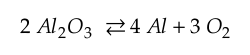
As temperature increases, the propensity is for this relationship to move to the left. So if this reaction is to occur, oxygen needs to be reduced in the surrounding environment. If the reaction takes place, then there is Aluminum available to form an intermetallic as shown below.
The oxygen could be reduced from the environment via one of the following relationships.
So a potential mechanism that leads to the formation of a lower melting point intermetallic would include the following steps:
- SiC reacts with oxygen.
- Oxygen leaves the environment, and some of the alumina breaks down.
- Aluminum is freed up and is in contact with the Pt-Rh wires.
- The Al and Pt form an intermetallic and the thermocouple wire fails.
Looking at a complex failure analysis that may involve mechanical, electrical, and chemical failure modes? Drop us a line and let’s discuss your needs to see if we can assist you with your failure.